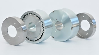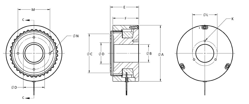
The bearings must be provided by the machine designer. The pole/case assembly and the rotor are shipped as separate items and it is the responsibility of the machine designer to ensure proper alignment and concentricity of the mating brake parts in the final assembly.
The mounting structure for these parts must be such that concentricity between the rotor OD (outside diameter) and the case ID (inside diameter), which forms the outer segment of the air gap, does not exceed 0.015 mm (0.0006”). Additionally, the run- out of the rotor face should not exceed 0.025 mm (0.001”).
|
MODEL |
DIA A |
DIA B |
DIA C |
DIA D |
E |
F |
K |
DIA L |
DIA M |
DIA N |
| LB-250M |
112.5 |
28.0 |
70.0 |
36.0 |
54.5 |
50.5 |
M5 X 10 |
45.0 |
54.0 |
5.3 |
| LB-450M |
137.5 |
42.0 |
90.0 |
50.0 |
57.0 |
52.5 |
M5 X 10 |
60.0 |
80.0 |
4.6 |
| LB-750M |
158.0 |
50.0 |
110.0 |
60.0 |
80.0 |
73.0 |
M6 X 12 |
70.0 |
90.0 |
5.5 |
| LB-1750M |
226.0 |
80.0 |
160.0 |
120.0 |
83.0 |
76.5 |
M6 X 12 |
100.0 |
140.0 |
5.5 (8X) |
